
Masonry has been used successfully in building construction in the Northwest region (Washington, Oregon, and Idaho) for many decades as both the primary structural system and as a cladding material. Masonry has withstood the test of time not only because of its natural resistance to fire, water, impact, and organic growth but also because of its design versatility.
Historically, structural mass masonry wall systems such as that shown in Fig. i-1 were commonplace, primarily due to their superior fire- resistance, durability, and weatherability. Over time, such systems have given way to alternative structural/ framing materials and separate cladding elements. By definition, mass structures above-grade functions of walls, including control of water, air, heat, sound, and fire. Thus, replacing the mass structure increases the complexity of the wall design as follows:
Traditional decorative and durable cornice and cornerstone elements and strategically located built-in drip edges were typical of mass masonry structures. These were also responsible for deflecting much of the water cascading down the face of these buildings. These design elements have been either eliminated or traded for more modularized and economized veneer units that, while reminiscent of historic mass masonry construction detailing, do not have the same water- deflecting characteristics. Fortunately, most veneer wall assemblies are able to accommodate the added moisture ingress due to a concealed drainage plane and flashings. The result is a similar material aesthetic, fire-resistance, and durability, yet a flatter and simpler appearance, such as that shown in Fig. i-2, that lacks the intrinsic ability to deflect water away from the masonry-clad wall face and away from areas most sensitive to water entry, e.g., wall penetrations such as vents, windows, and doors.
Though the evolution of the above-grade wall design has led to more complex overall systems, product selection, and code compliance than in previous years, it has also demonstrated the durable and accommodating nature of modern above-grade masonry wall systems to the local climate conditions of the Northwest region.
As a result, the focus of this guide is to provide comprehensive design and construction detailing information for 8 primary above-grade wall systems successfully used in the Northwest climate that are composed of clay or concrete masonry as an adhered or anchored veneer or single-wythe concrete masonry unit (CMU) wall application. The focus for each system is to clarify the overall above-grade wall building enclosure design as it relates to managing moisture (both liquid water and vapor), air, and heat transfer between the interior environment and exterior environment and to demonstrate the constructibility of these systems to provide long-term durability. Cladding considerations including attachment and installation methods are also addressed.
Each system within this guide is addressed specific to the Northwest region, including Washington, Oregon, and Idaho and considers local climate, codes, and building preferences and practices. The systems included within this guide have also been developed for application to occupied multistory, multifamily residential or commercial structures with typical indoor environments (e.g., ASHRAE 551–compliant spaces) in the Northwest region. Multistory applications of each system are recommended in the “Masonry Systems Comparison Matrix” beginning on page i-8. Although, some of the systems discussed within this guide may be applicable to structures with atypical indoor environments (e.g., natatoriums, fridge and freezer warehouses, unconditioned spaces, etc.), these applications are not the intended scope of the guide.
The information presented within this guide is not meant to be exhaustive of all system variations, product performance properties, or detailing approaches but rather represents a selection of the successful enclosure design and construction practices used in the Northwest region.
This guide is not intended to replace professional advice. When information presented here is incorporated into specification building projects, it must be reviewed by the design team and reflect the unique conditions and design parameters of each building in addition to conforming with local building codes, standards, and by-laws.

Fig. i-1 Historic Masonry Structure: Maple Leaf Gate, Seattle 1911

Fig. i-2 Contemporary masonry veneer structure, Wenatchee Valley College Music and Art Center, constructed in 2012
This introductory chapter showcases the 8 primary above-grade wall systems that are the focus of this guide. This introduction also contains technical references and supporting information for general topics that apply to the featured above- grade wall systems.
Each subsequent chapter is dedicated to one of the primary above-grade wall systems and provides system-specific discussion, guidance, photos, and/or diagrammatic illustrations. Two- and three-dimensional details and cutaway wall sections are provided at the end of each chapter, summarizing the chapter content and illustrating its use in real-world-like applications.
The sections following the 8 system chapters contain additional information regarding thermal modeling parameters, product resources, and a glossary of terms.
The 8 primary above-grade wall systems featured within this guide are shown in Fig. i-3, and are summarized in the “Masonry Systems Comparison Matrix” beginning on page i-8. These systems and their respective chapters include:
Chapter 1: CMU (or Concrete Alternate) Wall with Anchored Masonry Veneer
Chapter 2: Steel-Framed Wall with Anchored Masonry Veneer
Chapter 3: Wood-Framed Wall with Anchored Masonry Veneer
Chapter 4: Integrally Insulated CMU Wall
Chapter 5: Interior-Insulated CMU Wall
Chapter 6: CMU Wall with Adhered Masonry Veneer
Chapter 7: Steel-Framed Wall with Adhered Masonry Veneer
Chapter 8: Wood-Framed Wall with Adhered Masonry Veneer (Thick or Thin Bed Method)

Fig. i-3 Chapters 1 through 8 system summary. Systems are depicted in plan view with interior located at left and exterior located at right.
As shown in Fig. i-4, the expected service life for various drained and mass wall systems will vary. A drained cladding system assumes that a drainage cavity exists between the back of the cladding and the water-resistive barrier (WRB) membrane and that exit pathways are provided to divert water within the cavity back to the exterior environment. Undrained cladding systems are not addressed in this table due to the decreased expected service life of such assemblies, which in turn reduces the effective service life of the cladding. We acknowledge decades-old undrained systems exist, but modern undrained assemblies in weather exposed conditions are at a higher risk of failure than modern drained systems.
The actual cladding service life within the depicted ranges will depend on cladding exposure, the quality of the original installation (including appropriate detailing at details and interfaces, etc.), and a continuous maintenance program. However, general field observations performed by RDH Building Science Inc. identify that concrete masonry unit walls (either coated or uncoated) and anchored clay masonry veneer walls can provide similar or greater expected cladding service life than other systems. This performance is primarily due to the lack of moisture- sensitive components of CMU wall systems or the inclusion of drainage provisions of veneer walls.
The following can help achieve average or greater service life of the masonry veneer–based cladding systems described above:
☑Immediately: Correct water diversion mechanisms that may have become disconnected or failed, such as scupper, gutters, or downspouts.
☑As Needed:Repair localized cladding and cladding component damage or failure.
☑Every 2 to 5 Years: Review cladding for signs of distress or wear such as cracks/spalling, efflorescence (see page i-66), organic growth development, or sealant joint failures and repair or clean as needed. Repair moisture sources that may be causing efflorescence.
☑Every 5 to 10 Years: Review the condition of mortar in masonry veneer walls; repoint mortar as necessary. Perform a comprehensive condition assessment of cladding and cladding components including sounding of adhered veneer components.
☑Every 5 to 20 Years: Reapply masonry sealers based upon sealer manufacturer–recommended intervals (see page i-59).

Fig. i-4 Expected cladding service life, based on a combination of manufacturer warranties and RDH staff professional opinions and experience
For the purposes of this guide, a masonry system is an above-grade exterior wall assembly that includes masonry as the primary cladding element and is designed for the local climate or microclimate where the system will be installed. A masonry system considers how all wall components (e.g., water control and air control layers, cladding attachment and supports, veneer products, etc.) are integrated and made continuous with all other wall elements, including the field-of-wall area and its relationship to penetration and transition details.
The system comparison matrix assists with the selection of appropriate masonry system(s) for a particular project. On the following fold-out pages, each system is described and compared according to the categories described on this page (below) and page i-13.
Recommended Occupancy | Residential occupancy includes multifamily structures with dwelling and/or sleep units. Commercial occupancy includes all other occupancy types. Both residential and commercial occupancies assume normal indoor environmental conditions as discussed on page i-2.
Maximum Building Height | The maximum building height recommended for each system is determined by typical wind pressures, common building shape/form, and accessibility for installation and maintenance. Building height definitions vary throughout the industry; however, for the purpose of this guide, building height is classified as either low-, mid-, or high-rise. Some systems may be used for buildings of greater height, but these applications should be carefully evaluated by the project’s design team.
Maximum Annual Rainfall Level | Defines the maximum annual rainfall level for each system as it correlates to the annual rainfall levels described in Fig. i-8 on page i-17. The recommended system level assumes high exposure of the cladding (minimal overhangs, canopies, or dense surroundings such as heavily treed areas or taller adjacent buildings). Note that the severity of regional rainfall can be minimized by implementing building form and feature practices that minimize exposure to rainfall (see page i-18). For example, a system designated with a maximum moderate level could be appropriate in extreme rainfall areas if roof overhangs are provided. Each building’s location and form are unique and should be considered when selecting a system.
Typical System R-value | Defines the typical effective R-value for the field of wall area. For veneer systems, this assumes that framed wall cavities contain insulation and that exterior insulation is installed at thicknesses necessary to maintain prescriptive energy code compliance as further clarified in thermal modeling results of each chapter. For single-wythe masonry systems, typical assumes an 8-inch concrete masonry unit (CMU) wall and either integral or interior insulation commonly installed in the Northwest region. Thermal performance can vary with wall depth, insulation type and thickness and cladding attachment methods. Refer to the chapter thermal performance tables referenced in the matrix for additional discussion.
Cladding Attachment (Lateral Loads) | Defines the attachment method used to laterally support the masonry veneer (where applicable).
Cladding Support (Gravity Loads) | Defines the attachment method used to support the gravity loads of the masonry component of the system.
Fire-Resistance Rating | Defines the ability of a building element or assembly to withstand exposure to a fire without passage of excessive heat, hot gases, or flames while continuing to provide sufficient structural stability. Typical ratings are shown. Chapter 4 and Chapter 5 ratings assume an 8-inch-wide CMU wall. Thicker CMU walls may achieve a higher rating.
Price Per Square Foot | Defines the relative price per square foot for components outboard of the wall sheathing (framed systems) or CMU backup wall structure. For single-wythe CMU without a veneer, pricing includes all components except interior finishes and interior framing (where it occurs). Pricing is based on a 10,000-square-foot wall area and is valid for the 2018 calendar year. Current pricing is also available at masonrysystemsguide.com.
The remaining sections within this introduction serve as a reference for topics discussed within many of the system chapters. These topics include the building enclosure and loads; building enclosure control layers; system rain control strategies; thermal performance and energy code compliance; sheet- metal components; movement joints; cleaning, repellents, and coatings; and minimizing freeze-thaw cycles and efflorescence.
The content of this guide and additional information may be accessed online at www.masonrysystemsguide.com. Also available online are downloadable digital versions of two- and three-dimensional system details and cutaway sections and sample project specifications. Ongoing additions to the references and resources included within this guide can also be accessed.
The building enclosure (i.e., building envelope) is a system of materials, components, and assemblies physically separating the interior environment(s) from the exterior environment. As an environmental separator, the enclosure must control the flow of heat, air, water (liquid water and water vapor), sound, and much more. The building enclosure must also provide support against physical loads on the building (e.g. air pressures, gravity loads, impact, etc.) and, in most, but not all cases, is required to provide an acceptable interior and exterior finish and help distribute utilities through the building.
An appropriately designed building enclosure benefits a building’s heating and cooling energy use, comfort, durability, and serviceability. It also contributes to a healthy indoor environment.
The elements of the building enclosure include roofs, above- and below-grade walls, windows, doors, skylights, exposed floors, the basement/slab-on-grade floor, and all of the interfaces and details in between. Many typical building enclosure elements are depicted in Fig. i-5. Because the focus of this guide is specific to the 8 primary masonry systems described in the previous sections, only design considerations for above-grade wall systems are addressed here. Where appropriate, roof, floor-line, foundation, and fenestration transition details, in addition to typical wall penetration details, are also discussed.

Fig. i-5 Many building enclosure elements are visible in this photo, including a roof, above- grade walls, windows, doors, and floors (i.e., so its).
Over the life of a building, the building enclosure is subjected to a wide range of interior and exterior environmental loads. The impact of rain (liquid water) falling on and flowing over the exterior surface of the building—as well as differences in temperature, water-vapor content, and air pressures between the interior and exterior environments—creates the most critical loads acting on the enclosure.
Interior environmental loads include building pressures, temperature, relative humidity, and water vapor condensation as well as liquid water and water vapor associated with the operation of heating /cooling and ventilation systems, human activities, and potential defects in appliances, sprinklers, and interior plumbing.
Exterior environmental loads include solar radiation, rain, snow, ice, hail, vapor condensation, wind, temperature, relative humidity, insects, pests, and organic growth. The climate zone in which the building is constructed, in addition to its site-specific features, dictates the magnitude and duration of these environmental loads.
As depicted in Fig. i-7, three climate zones exist in the Northwest: Marine Zone 4, Zone 5, and Zone 6. These climate zones impose a wide range of environmental loads, including rainfall ranging from low to extreme levels as shown in Fig. i-8 and Fig. i-9. In the Northwest, high and extreme rainfall loads occur near the western Washington peninsula, the Oregon coast, and the higher elevations of Idaho.
Site-specific features, including the local terrain, can further vary the properties of the regional exterior climate by creating a microclimate specific to a building site. For example, whereas a project may be located in a regional high-wind area, the site’s features such as adjacent buildings or heavily wooded areas could reduce the wind exposure on the building.
Region and site-specific climate determine the potential for water (e.g., rain, snow, hail), solar, and wind loads on the building enclosure. However, a building’s form and features dictate to what degree these loads act on the building enclosure. On a larger scale, building form and features include the building height as well as geometry inclusive of canopies, balconies, and roof overhangs. On a smaller scale, form and features include cladding, fenestrations, cornice elements, counterflashings, and drip edges all act as part of the water-shedding surface.
Specific to above-grade wall systems, exterior architectural elements such as balconies, canopies, or roof overhangs can deflect large amounts of water away from fenestration systems, cladding elements, and building entrances. Examples of beneficial building form and features are shown in Fig. i-10, Fig. i-11, and Fig. i-12. Conversely, building form and features can increase the severity of loads such as water by concentrating runoff at specific areas of the building enclosure. For example, a canopy that drains water runoff onto the wall cladding could cause staining, cladding damage, or worse: water intrusion into the building. In the Northwest region, it is especially critical in moderate to extreme rainfall areas that a building’s form and features are consciously designed for water control.
The water-shedding surface is the outer surface of the masonry system: the anchored or adhered veneer or CMU wall face at the field-of-wall area. The water- shedding surface also extends to the details and transitions shown throughout this guide and includes sheet-metal flashings, the face of fenestrations (e.g., windows), the roof membrane of a conventional roof assembly, and the top surface of the insulation of an inverted roof assembly.
The water-shedding surface will deflect and/or drain the vast majority of the exterior water from the system; thus, the water-shedding surface reduces the water load on the underlying elements of the system. Due to its importance, the water- shedding surface is depicted on the system figures and details throughout this guide as shown in Fig. i-14 and Fig. i-15 on page i-22.
In summary, interior climate, exterior climate (both regional and site-specific microclimate), and a building’s form and features, including the water-shedding surface, all determine the overall water, air, heat, and vapor loads that act on the building enclosure. Together these factors may be referred to as load-determining factors and are graphically summarized in Fig. i-13 on page i-21.

Fig. i-6 United States climate zone map as referenced from Figure C301.1 of the 2015 International Energy Conservation Code.3

Fig. i-7 Northwest region (Washington, Oregon, and Idaho) Climate zones including Zone Marine 4, Zone 5, and Zone 6 as references from Figure C301.1 of the 2015 International Energy Conservation Code3 (see Fig. i-6).

Fig. i-8 United States Total Annual Rainfall Levels. Map by RDH Building Science Inc. Data courtesy of National Oceanic and Atmospheric Administration.4

Fig. i-9 Annual rainfall levels of the Northwest region. Figure excerpted from Fig. i-8.

Fig. i-10 ICHS Shoreline Medical and Dental Clinic, constructed in 2014, features large roof overhangs and canopies above entrances to deflect rain away from the above-grade enclosure components and shade the interior environment from the sun.

Fig. i-11 (above) Baker Middle School (opened in 2012) showcases roof overhangs that assist in deflecting rainwater away from the building enclosure below. Sun shades over windows also assist with controlling solar loads and reducing rain exposure.

Fig. i-12 (right) At Station 38, Hawthorne Hills, sheet-metal drip edges above windows, projected precast concrete windowsills, roof gutters, downspouts, and window canopies all help reduce the amount of water on the building enclosure.
As discussed, a function of the building enclosure is to control (i.e. appropriately manage) building enclosure loads such as water (precipitation and ground), water vapor, air, heat, sound, fire, light, and contaminants. For the purpose of this guide, water, air, heat, and water vapor (i.e. vapor) are addressed in greater detail. Consideration of sound, fire, light, and contaminants may be related to the concepts discussed within this guide but are not covered in detail.
Water, air, heat, and vapor are controlled by various layers including the water control layer, air control layer, thermal control layer, and vapor control layer, respectively. These layers may include systems of materials or stand-alone materials that are intentionally selected and located within the enclosure to control a specific enclosure load. Fig. i-13 depicts the relationship between the concept of load-determining factors, building enclosure loads, control layers, and the systems and materials that make up each control layer.
When control layers are intentionally designed to control a specific load, they are said to have a primary relationship with the building enclosure load. Primary relationships are shown in Fig. i-13 with a solid line connecting the building enclosure load and control layer. Some control layers will also assist with the control of other loads. This relationship is shown in Fig. i-13 as a dashed line connecting the building enclosure load and control layer.
Using the control layer concept to evaluate assemblies and details (e.g. masonry systems) is consistent with industry best practices and can be useful to assess specific assemblies and details being considered for a project. The application of the control layer concept can help all parties better understand the role and importance of the systems and materials associated with each layer and can help identify areas where control layers may be missing or are discontinuous (if required to be continuous). Throughout this guide, the control layers are shown on system figures similar to those shown in Fig. i-14 and Fig. i-15 on page i-22. Placement and continuity of these systems and materials are also shown for each 2-dimensional detail in the system chapters.
As an example, the building enclosure load of air—more specifically air pressure—is controlled by the air control layer (the primary relationship). This layer comprises the air barrier system. The air control layer also has secondary relationships: it assists with controlling water, heat, water vapor, sound and fire.

Fig. i-13 Building enclosure load and control layer relationships, specific to the above-grade wall systems and details depicted in this guide.

There are three categories of rain control available for above-grade walls: screened and drained (i.e., rainscreen), storage (i.e., mass), or perfect barrier.5 The systems within this guide include either rainscreen or mass walls. Perfect barrier walls are not included; however, perfect barrier assemblies or materials such as a conventional roof membrane assembly or window glass occur in some details. Further discussion of the perfect barrier category of rain control is beyond the scope of this guide, though a definition of a perfect barrier system may be found in the glossary.
A rainscreen wall is shown in Fig. i-14. This rain control category assumes that some water makes its way through the cladding plane while the building is in- service. For the purpose of this guide, a rainscreen wall assumes the following characteristics:
A continuous air control layer is not a requirement of the rainscreen wall but is typically provided in the Northwest region to improve rain control and meet energy code requirements.
The masonry systems in Chapters 1, 2, 3, 6, 7, and 8 are rainscreen walls with respect to rain control and are referred to as rainscreen wall systems in this guide.
A mass wall is shown in Fig. i-15 on page i-22. In recent years, the mass wall rain control strategy has evolved to allow for thinner mass wall systems that further control water through the use of clear surface-applied water repellents and water-repellent admixtures.
The systems in Chapters 4 and 5 are mass walls with respect to rain control and are referred to as mass wall systems.
It is important to note that rainscreen wall systems can exhibit good resistance to water penetration and are less sensitive to water ingress than other rain control categories; however, good performance is reliant on implementing proper details and ensuring acceptable construction practices are followed. Improperly executed details are frequently sources of water intrusion, critically affecting the moisture performance of the assembly and contributing to premature weathering or efflorescence on the masonry veneer system.

Fig. i-16 Typical window head two- dimensional detail. Each colored line or shaded area corresponds to the control layer identified in the legend below the detail.
As described in Fig. i-13 on page i-21, each control layer is primarily responsible for managing a specific building enclosure load. The control layers and the systems and/or materials that make up each system are described in detail in this section are summarized in each system chapter and depicted on the typical wall assembly figures and 2-dimensional details throughout this guide (as shown similarly on Fig. i-16).
The water control layer is a continuous control layer that is designed, installed, and/or acts to form the innermost boundary against water intrusion.
In a rainscreen wall system, the water-resistive barrier (WRB) system is the last line of defense against water intrusion. A WRB system includes a WRB field membrane and accessories such as fluid-applied and flexible flashing membranes, sheet- metal flashings, sealants, tapes, and fasteners. To be effective, these materials are continuous and shingle-lapped to promote water-shedding. Where the WRB system is also part of the air-barrier system, it will be sealed for airtightness using tapes, sealants, gaskets, and other components.
A WRB system generally has the following properties:
For the rainscreen wall systems discussed in this guide, the WRB field membrane may be either a sheet- or fluid-applied membrane installed over the wall sheathing/structure as shown similarly in Fig. i-17. The field membrane may also be the face of fully taped or sealed exterior insulation that exists outboard of the wall sheathing or structure. In this guide, two WRB field membrane types are discussed and demonstrated in details; these include sheet-applied (either mechanically attached or self-adhered) and fluid-applied membranes. Examples of each system are shown in Fig. i-17 and in Fig. i-18 on page i-27.
For the mass wall systems included within this guide, the WRB system is the single-wythe CMU wall structure inclusive of a surface- applied clear water repellent and integral water-repellent admixtures within the block and mortar.
The air control layer is provided by the air barrier system and is responsible for controlling the flow of air through the building enclosure, either inward or outward. Air flow is significant as it impacts heat flow (space conditioning), water vapor transport, and rain penetration control.
The air barrier system should be impermeable to air flow, continuous across the building enclosure, strong enough to transfer the forces that act upon them (e.g., mechanical pressures, wind pressures, and stack effect) back to the structure, durable over the life expectancy of the building enclosure, and stiff enough to resist air flow without altering its other performance characteristics.6 Additional discussion on the degree of air impermeability of the air barrier system is further discussed in Code Airtightness Requirements discussion on page i-43.
For a rainscreen wall system, there are many types of air barrier systems available on the market today. A typical practice within the Northwest is to use the wall system’s WRB system as the air barrier system. If implemented, the WRB system must have the properties of an air barrier system and must be taped and/or sealed continuously for airtightness.
Where the air barrier system is a mechanically attached sheet membrane, it is secured to the structure with furring strips, masonry ties, cladding support clips, or washer head fasteners as approved by the air barrier membrane manufacturer. This attachment assists with long-term resistance to the pillowing effects of air pressure differentials. Where a self-adhered sheet membrane or fluid-applied membrane is used, the membrane bonds directly to the exterior sheathing or substrate for continuous support.
Other types of air barrier systems include:
For the mass wall systems within this guide, the single-wythe CMU wall structure may provide the air barrier system as further discussed in the Air Control Layer on page 4-3 or may use other products as discussed in the Air Control Layer discussion on page i-26.
The air barrier system extends to the details and transitions shown throughout this guide and includes fenestration systems, the air barrier membrane of a conventional roof system, and the roof membrane of an inverted roof membrane system as well as spray foam (of a minimum thickness, often determined by manufacturer testing) and sealant joints necessary to transition between assemblies.
Code-required air barrier system performance targets specific to the Northwest region are discussed in the Code Airtightness Requirements discussion on page i-43.
The vapor control layer retards or greatly reduces the flow of water vapor due to vapor pressure differences across the building enclosure. The ease with which water molecules diffuse through a layer is known as vapor permeance. The 2015 International Building Code (IBC)8 defines three classes of vapor permeance:
Although not defined by the IBC, a Class IV vapor permeance designation is o en used for materials that have a vapor permeance > 10 perms.
A vapor control layer may not be necessary for some masonry wall systems (such as Systems 1, 4, and 6) in the Northwest region and is further discussed in each system chapter. Perfect continuity of the vapor control layer is also not necessary to adequately control vapor diffusion in most cases. Small holes, gaps, or tears are not critical, unlike with the air barrier system. Section 1405.3 of the 2015 IBC defines code requirements for vapor control in Northwest Climate Zones 5, 6, and Marine 4. In the Northwest region, a vapor retarder (Class II vapor permeance) material is commonly installed on the interior (warm in winter) side of the insulation (high vapor pressure side), such as inboard of framing in Systems 2, 3, 7, and 8. Common vapor retarder products include:
Note that for Systems 2, 3, 7, and 8, the use of a polyethylene sheet (Class I vapor permeance material) is not generally recommended for vapor control in the Northwest region because it significantly reduces the inward drying ability of the wall system which can be beneficial to some systems during warmer seasons.
Whereas all materials fall into a class of vapor permeance, it is important to consider the vapor permeance of each material within the wall system relative to the building’s thermal control layer (e.g., the vapor permeance of the air barrier and WRB system relative to cavity and/or exterior insulation).
In the Northwest region, it is generally acceptable to locate:
Class III permeance materials and their placement within the wall system should be carefully considered on a case-by-case basis. The locations for each class permeance described above assume typical interior conditions as described in introductory text of this chapter.
The thermal control layer is responsible for controlling the heat flow across the building enclosure. The placement and continuity of the thermal control layer is an important factor of a thermally efficient building enclosure. While all materials within the building enclosure contribute to the thermal control layer, some materials may actually increase heat flow (such as highly conductive framing elements). Identification of high-conductivity materials helps identify thermal bridges or any thermal discontinuities that should be addressed by design.
Materials that contribute most to slowing the rate of heat flow across the wall system include thermal insulation, low-conductivity framing elements, and thermally improved glazing systems. These materials are identified in the control layer diagrams found throughout this guide.
For a rainscreen wall system, the primary resistance to heat flow is provided by thermal insulation within the framed wall cavity (if applicable) or by exterior insulation within the air cavity between the air barrier and WRB system and the cladding. Wood framing components will provide some insulating value, whereas steel stud framing will not.
For the mass wall systems in this guide, the thermal insulation is either interior of the CMU structure or integral at CMU cores.
A variety of insulation products exist on the market for wall cavities, integral insulation, and continuous (interior or exterior) insulation.
For wall cavities, unfaced fiberglass or mineral fiber batt are most common. High-density versions of either batt can be found and assist with achieving a greater effective R-value without increasing wall depth, especially in wood-framed wall systems. Due to the significant reduction in effective thermal performance for steel-framed wall systems (typically 40 to 60%), a high-density batt provides little benefit over lower-density batt products in steel-framed systems. Batt insulation widths and thicknesses range in size to accommodate most standard wood and steel framing depths. Wall cavity insulation may also include sprayed polyurethane foam insulation, which is available in both open- and closed-cell varieties and varies in thermal resistance and vapor permeance.
Where split insulation occurs (e.g., both wall cavity and exterior insulation) it is important to consider both the air and vapor permeance of the insulating material and the air barrier and WRB system. These considerations are discussed in each system chapter.
Where continuous insulation is used, several types of insulation products are available:
Integral insulation, which may be used within the CMU systems of this guide, may be loose-fill such as perlite but is commonly provided by a foam-in-place insulation product. Foam-in-place insulation is typically injected through ports within the CMU mortar joints. An example of foam-in-place insulation is shown in Fig. i-22.

Fig. i-17 Sheet-applied air barrier and water- resistive barrier membrane example

Fig. i-18 Fluid-applied air barrier and WRB membrane example

Fig. i-19 Polyamide film vapor retarder installed over a wood-framed wall with cavity batt insulation
For above-grade wall assemblies in the Northwest, low-permeance exterior insulation and air barrier and WRB systems may be used when all insulation is located exterior of the air barrier and WRB system or when the exterior insulation is 1/2 to 2/3 of the total nominal insulation R-value of the system. This helps reduce the risk that condensation will develop inboard of the air barrier and WRB system. In all cases, the use of low-permeance products and their placement relative to thermal control layer elements should be carefully evaluated based on project-specific characteristics.

Fig. i-20 Semi-rigid mineral fiber insulation prior to anchored masonry veneer installation
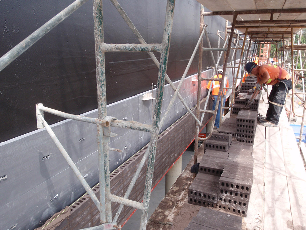
Fig. i-21 XPS insulation behind anchored masonry veneer
Although masonry is defined as a noncombustible cladding material, the use of combustible air barrier and WRB system products or foam plastic insulation products within a wall cavity can trigger fire propagation considerations and requirements. Depending on the local jurisdiction, IBC Section 1403.5 regarding vertical and lateral flame propagation as it relates to a combustible air barrier and WRB system may require acceptance criteria for NFPA 2858. The use of foam plastic insulation within a wall cavity should also be addressed for IBC Chapter 26 provisions.
At the time of publication, the energy performance of buildings in the Northwest is governed by:
In general, these energy codes address the minimum requirements for both the air and thermal control layers of the opaque above-grade wall systems.
In this guide, discussions related to the energy code compliance focus on the above-listed codes and their commercial energy code compliance provisions; residential provisions are not addressed. Definitions of residential and commercial buildings may be found within the Definitions chapter of the codes listed above.
Under commercial provisions, the prescriptive performance requirements for opaque above-grade wall systems are differentiated by:
Table i-1 on page i-38 summarizes the prescriptive opaque above-grade wall thermal envelope insulation requirements as they apply to the wall systems in this guide. Requirements for both the minimum R-value method and maximum U-factor method are included. In Table i-1:
Fig. i-26 on page i-39 describes the typical process for navigating the opaque above-grade wall system thermal envelope energy code compliance options and strategies. It also describes how this process relates to the system-specific thermal performance results and discussions included within each system chapter of this guide.
Refer to Fig. i-26 on page i-39, which identifies the prescriptive compliance options for energy code compliance. Where a project seeks this compliance option, the above-grade wall system must meet one of the following strategies:
An exception to the compliance strategies listed above is denoted in Footnote 2 of Table i-1 on page i-38. Refer to Chapter 4 for more information regarding this exception.
Refer to Fig. i-26 on page i-39, which identifies the non-prescriptive compliance option (e.g., whole-building modeling strategies). When a project seeks this compliance option, an above-grade wall assembly’s thermal performance is determined as a U-factor; however, it may or may not be required to meet the prescriptive values shown in Table i-1.
Various thermal performance tables are available in the Northwest energy codes and ASHRAE 90.113 to assist with determining the U-factors of above-grade wall assemblies. Where the wall assemblies are not representative of a project specific application, alternative methods are available for calculating the effective thermal performance of the wall and are discussed below. Appropriate calculation methods should be confirmed with the authority having jurisdiction because not all of these methods may be accepted:
Within this guide, three-dimensional computer modeling was employed for all wall systems, except System 4, to demonstrate how typical thermal bridges—like masonry ties, shelf angles, and cladding support clips of various types—contribute to the effective thermal performance of insulation thicknesses and types as well as cladding support materials and types may be estimated for project-specific systems. Through evaluation of the results, numerous options for thermally optimizing each wall system are discussed. Modeling results and discussions are demonstrated in each chapter as an effective R-value but may be converted to a U-factor by dividing 1 by the R-value.
Thermal modeling was undertaken using HEAT3.16 Modeling specifics and additional information used to complete the modeling within this guide are provided in the Appendix. Modeling does not account for the impact of thermal mass.
Continuous insulation is referenced in the prescriptive requirements for many of the wall systems in this guide. Where continuous insulation is required or used to meet code compliance, the definitions of continuous insulation should be carefully considered; definitions vary by jurisdiction within the Northwest region and include:
Based on the above definitions:
☑Continuous insulation can be interior, exterior, or integral to the building envelope, for example, continuous insulation interior of a CMU wall as shown in the System 5.
☑Insulation bridged by structural members (e.g., framing or anchored veneer shelf angles) may not be considered continuous. This guide recommends clarifying this requirement with the governing jurisdiction on a project- specific basis.
☑Service openings (e.g., doors, ducts, etc.) have no impact on whether insulation is classified as continuous or not.
☑Fastener or metal fastener considerations vary by jurisdiction and are further discussed in the next section.
The thermal performance of exterior insulation is reduced when penetrated by fasteners (metal or otherwise). Continuous insulation with no fasteners will perform near its nominal R-value. However, when fasteners—especially metal fasteners, which are highly conductive—penetrate the insulation, the nominal R-value is reduced.
The interpretation of a fastener or metal fastener may vary by code and jurisdiction. As a result, the local governing jurisdiction should be contacted for determining when fasteners are to be considered. Below, some general clarifications are provided for assistance.
Under the 2015 SEC10, the fasteners’ cross-sectional area of penetration (as measured in the plane of the insulation surface and as calculated as a percentage of opaque wall area) should be considered. Where this area of penetration exceeds 0.04%, the penetrated insulation is not considered continuous or “continuous insulation equivalents” tables located within the code may be referenced. For example, if exterior insulation is bridged by a 2-inch-wide double eye and pintle masonry tie at 24-inches on-center vertically and 16-inches on-center horizontally, the cross- sectional penetration area as a percentage is:
Note that if the tie spacing was reduced to 16-inches on-center vertically and 16-inches on-center horizontally, the cross-section penetration area of 14-gauge backup plate tie would be greater than 0.04%. In this case, guidance provided for the 0.06% case above would be considered.
Under the 2014 OEESC11 and the 2015 WSEC9, fasteners that penetrate continuous insulation have no impact on whether exterior insulation is considered continuous or not for code compliance purposes. Table C402.1.3, Footnote (g) of the 2015 SEC10 and 2015 WSEC9 codes provides continuous insulation equivalent R-values for penetration areas exceeding 0.04% area.
When complying under the 2012 IECC12, contact the local governing jurisdiction to confirm metal fastener and continuous insulation requirements.
A mass wall has the ability to store thermal energy (i.e., heat) that can be released at a later time, reducing peak heating and cooling loads and increasing occupant thermal comfort. The benefit of thermal mass varies with climate zone and is more beneficial in warmer climates; however, thermal mass can still provide some benefit in cooler climates. Some energy codes within the Northwest allow mass wall systems to meet lesser prescriptive thermal performance requirements than framed wall types. When complying with the energy code through a whole- building modeling approach, any effects of thermal mass are directly considered within the building model.
The 2012 IECC12, 2015 WSEC9, 2015 SEC10 and 2014 OEESC11 in general define mass wall as weighing more than 35 psf of wall surface area or weighing more than 25 psf of wall surface area when the material weighs more than 120 pcf. Furthermore, the 2015 WSEC9 and the 2015 SEC10 clarify that mass walls may also include walls having a heat capacity that exceeds 7 Btu/ 2-deg F or walls having a heat capacity greater than 5 Btu/ 2-deg F when the material weight is not more than 120 pcf.
The classification of a mass wall typically encompasses the backup wall structure; veneer inclusions should be confirmed with the local governing jurisdiction. The masonry systems in Chapters 1, 4, 5, and 6—which have CMU backup wall structures—typically qualify as mass walls.
In the states of Oregon and Washington (excluding the City of Seattle), integrally insulated CMU walls such as the masonry system in Chapter 4 system are exempt from some prescriptive performance R-values and U-factors when specific conditions are met. See the discussion in Chapter 4 for more information on this exception.
Energy codes within the Northwest have mandatory air leakage requirements. Requirements include a continuous air barrier throughout the building thermal envelope (i.e., surrounding conditioned and semi-heated spaces) that is continuously sealed and supported by the structure (e.g., with fasteners or adhesion). Air barrier system compliance options for each Northwest code are provided below. This guide recommends that all members of the design and construction team are familiar with the air barrier system requirements specific to their jurisdiction.
The following checklist items can increase the success of the design and installation of a continuous air barrier in all jurisdictions.
☑Select appropriate air barrier system materials and assemblies. Per the IECC,3 an air barrier material has an air permeance less than 0.004 cfm/ft2 at 1.57 psf (75 Pa) when tested to ASTM E2178.19 An air barrier assembly has an air permeance of less than 0.04 cfm/ft2 at 1.57 psf (75 Pa) when tested to ASTM E2357.20 Section C402.4 of the 2012 IECC and Section 502.4 of the 2014 OEESC11 include a number of air barrier materials and assemblies that meet these requirements. The Air Barrier Association of American (ABAA) also lists several commercially available compliant air barrier membrane products and systems at www.airbarrier.org.
☑Ensure that a continuous line representing the plane of airtightness can be drawn across building enclosure assemblies, details, and transitions between assemblies. This includes in both plan and section perspectives. Details included within this guide demonstrate this practice, and an example is shown in Fig. i-16 on page i-24.
☑Clearly delineate the air barrier system’s pressure boundary on the construction documents. This practice is typically performed on the floor plans for each building level and on each building section as shown in Fig. i-28. This delineation, in addition to the calculation of the air barrier pressure boundary surface area, is required by the 2015 WSEC9 and the 2015 SEC10 for compliance.
☑Identify air barrier system installation, testing, and installer qualification requirements in Divisions 1 and 7 of the project manual. Air barrier master specifications related to Divisions 1 and 7 are available from ABAA’s website and may be modified to meet local code and project specific requirements.
☑Use installers with air barrier system installation experience to perform air barrier–related installations.
☑Designate an air barrier/building enclosure foreman or superintendent from the construction team to oversee all trades involved in installations related to the air barrier.
☑Build freestanding mock-ups of all project-specific typical and unique air barrier details. Retain building mock-ups for training and reference purposes throughout construction.
☑Perform qualitative diagnostic air leakage testing of mock-up installations to identify deficiencies. Correct deficiencies and retest to demonstrate that deficiencies have been resolved. Refer to ASTM E118621 for air leakage site detection practices. An example of diagnostic air leakage testing is demonstrated in Fig. i-29.
☑Implement a quality control program. Develop a checklist of items requiring review prior to covering the air barrier system with additional elements such as exterior insulation and cladding.
☑Provide third-party quality assurance reviews of installed air barrier detailing and provide periodic diagnostic air leakage testing to confirm airtight transitions, especially between roof-to-wall, roof-to-foundation, floor line, and window perimeter detailing.
☑Execute whole-building air leakage testing prior to covering (when possible). This limits the need to remove building elements, such as cladding, to correct deficiencies.

Fig. i-22 Foam-in-place CMU core insulation

Fig. i-23 Northwest region climate zones as referenced from Fig. i-17
The IECC3 defines the building thermal envelope as “the basement walls, exterior walls, floor, roof, and any other building elements that enclose conditioned space or provide a boundary between conditioned space and exempt or unconditioned spaces.” Note that the thermal envelope may not always occur at the building enclosure.
Project-specific thermal performance values for an opaque above-grade wall should be used for energy code compliance and determined from a source that is approved by the authority having jurisdiction. Thermal performance sources may include the Appendices of the 2015 WSEC,3 ASHRAE 90.1,4 COMcheck,5 thermal modeling and calculation exercises, or other industry resources.


When performing heat loss calculations (e.g., mechanical equipment sizing or energy modeling) the system’s U-factor, inclusive of all thermal bridges, should be considered.

Table i-1 Northwest energy codes – prescriptive compliance values for opaque above-grade wall systems within this guide

Fig. i-26 Energy Code Compliance Chart. Use this chart to navigate selection of an energy code compliance strategy and use of the modeling results within this guide.
The term “thermal bridging” is not defined by the energy codes that govern the Northwest region. However, the ASHRAE Handbook of Fundamentals15 recognizes thermal bridging as “passing highly conductive materials through insulation layers.”

Fig. i-27 Blower door setup during whole- building air leakage testing of a building with an anchored masonry veneer above- grade wall system

Fig. i-28 Whole-building section with the continuous air barrier system pressure boundary denoted in red

Fig. i-29 A smoke pencil is used to conduct diagnostic air leakage testing while a building is under positive air pressure; the smoke exits the building through a discontinuity at the head of the window rough opening.
Sheet-metal flashing components are used in both rainscreen and mass wall systems and typically occur above and below wall penetrations, at parapet tops, and as counterflashing elements. Sheet-metal flashings deflect rain water and protect underlying components among many other functions.
The location of sheet-metal flashings should be carefully each project, but—at they should be located:
It is best practice to provide sheet-metal flashing profiles which include a projected hemmed drip edge, positive slope, and a minimum 4-inch-tall back leg where the flashing is shingle lapped into the WRB system. Where serving as a counterflashing, it is best practice to counterflash cladding a minimum of 1.5-inches (where possible) and project a minimum of a half an inch beyond the cladding face to avoid blocking ventilation. The vertical location of the sheet-metal flashing in relation to the masonry veneer should be considered; adequate spacing between the sheet metal and the veneer above and below will ensure building movement does not adversely affect the sheet-metal flashing profile or its function.
In a rainscreen wall system, folded end dams assist with deflecting water away from the rainscreen cavity and are recommended at all flashing terminations (e.g., at the ends of a window head flashing).
Where sheet-metal laps occur, laps are either fully sealed with a high-quality silicone or butyl-based sealant or may be soldered.
It is a best practice to construct masonry veneer sheet-metal flashings from stainless steel. Stainless steel is relatively inert to the corrosiveness of mortar and provides a similar level of durability and longevity as the masonry veneer. Prefinished galvanized sheet-metal products may be used in masonry veneer applications; however, they may require replacement before the masonry veneer does.
This guide recommends consulting the Architectural Sheet Metal Manual22 published by the Sheet Metal and Air Conditioning Contractor’s National Association (SMACNA) for additional discussion on the design and installation of sheet-metal components.
Where exterior insulation is used, cross-cavity sheet-metal flashings create a thermal bridge. An alternative to a sheet-metal flashing at anchored veneer systems is to provide a flexible self-adhered flashing membrane that is fully supported by the exterior insulation and lapped into the WRB system as shown in page i-47. This flexible membrane is shingle-lapped over the bearing element (typically a standoff shelf angle) and under the sheet-metal drip flashing.

Fig. i-30 System 8, Detail 8b-D. Typical floor line cross-cavity sheet-metal flashing. The flashing helps drain the rainscreen cavity above and deflects water away from the top of the cavity below, while still allowing for drainage and ventilation in each cavity. Space above and below the sheet-metal flashing also allows for movement within the veneer as well as differential movement between the veneer and wall structure.
A cross-cavity flashing and through-wall flashing are commonly used interchangeably; however, there is a technical difference. A cross-cavity flashing is integrated with the WRB system and extends through the rainscreen cavity. A through- wall flashing extends through the entire depth of the wall, such as one might find at the base of a CMU wall.

Fig. i-31 System 2, Detail 2-D. Typical floor line condition at standoff shelf angle. This alternative detail approach includes a flexible self-adhered membrane in lieu of sheet metal to drain the rainscreen cavity.

Fig. i-32 Cross-cavity sheet-metal flashing displacement as a result of wood-framed wall shrinkage and brick anchored clay masonry veneer expansion
Over time, volumetric changes will occur within any above-grade wall system and can be the result of changes in temperature, moisture, elastic deformation, settlement, and creep. The amount of movement that occurs will depend on the building materials used within the wall system as well as on the intensity of the influencing mechanism (e.g., temperature change). In general, wood frame members, concrete, CMU, and stone will shrink, whereas clay masonry will expand. If steel studs or a CMU backup wall are used and are properly protected, minimal volume change is expected, except where specifically designed for.
Different materials within each wall system may move differently in relation to one another as shown by the example in Fig. i-32. If not properly designed for, differential movement can cause unwanted cracking, spalling, buckling, settlement, or separation within the building structure or veneer.
For the purpose of this guide, discussion and design of movement joints are considered as they relate to differential movement between the veneer and wall structure and also include control and expansion joints. The consideration for locating and sizing building expansion joints that occur within the wall structure is beyond the scope of this guide but must be appropriately designed for and integrated into the above-grade wall system where they occur.
The discussion of building movement in this guide is meant to be a general reference; it is the responsibility of the Designer of Record to appropriately design for all building movement.
This section identifies general rules for locating movement (expansion or control) joints as they relate to the 8 primary wall systems in this guide.
There is no single set of recommendations for the placement and design of movement joints that will work for all projects. Additionally, joints may be added more frequently than is necessary for aesthetic purposes. In general, the following locations for movement joints are recommended within a masonry veneer or structure in addition to the above.
Note that placement of horizontal joints is also recommended at various locations on a rainscreen wall system to allow for cavity drainage and building movement.
The location of joints for the purposes of accommodating movement, drainage, and/or veneer air cavity ventilation are further discussed and identified within each chapter and with an asterisk (*) in chapter details.
Joints that accommodate vertical movement either include a sheet-metal flashing or a backer rod and sealant joint. Joints that accommodate horizontal movement typically receive a backer rod and sealant joint. Movement joints are typically designed and constructed to accommodate 3 to 4 times the amount of anticipated movement but are no narrower than 3⁄8 of an inch. All allow for unobstructed movement, movement joints should be free of debris, reinforcing, or other elements that may inhibit movement over the life of the building.
Joint sealants are a critical component of a movement joint and allow the joint to open and close mostly uninhibited while providing a continuous water-shedding surface. Sealant products ideal for use at masonry movement joints have the following properties:
☑Movement Capabilities: A sealant that allows for expansion or compression of the sealant joint without permanent deformation. The sealant product selected should be classified as a Class 100/50 sealant per ASTM C920.29 This sealant has joint movement capabilities of a minimum 100% extension and 50% compression when tested to ASTM C719.30
☑Adhesion to Substrate: The sealant selected should have demonstrated adhesion to porous substrates such as masonry and concrete. Where differing substrates occur at either side of the movement joint (e.g., at metal panel–to- masonry veneer interfaces), the sealant should have acceptable adhesion to both substrates. Sealant adhesion testing prior to and during field installation is highly recommended and should result in cohesive sealant failure (rather than adhesive failure to the substrate).
☑Durability: Movement joints at cladding should be UV-stable as well as durable when exposed to moisture and temperature fluctuations.
☑Longevity: Masonry is a long-lasting cladding option and will likely outlive the sealant joint. To match the durability of the masonry cladding and reduce the replacement frequency of the joint, this guide recommends a quality silicone sealant. When properly installed and maintained as needed, silicone sealants will exhibit 20+ years of acceptable performance. Other sealant options such as hybrid or polyurethane sealants may provide acceptable performance for 10+ years before replacement is required.
The following joint design best practices will encourage long-term performance of a movement joint:
☑Select a quality sealant based on the criteria described in the Joint Design discussion on page i-51.
☑Follow industry-standard best practices for sealant joint installation. This includes joint design and substrate cleaning and priming. As a useful resource, refer to the Dow Corning Americas Technical Manual31 as well as the joint dimensioning described in Fig. i-34.
☑Provide an annual review and repair of joints one year a er installation and biannual reviews thereafter. Areas of adhesive failure or damage should be repaired.
Where there is a desire to minimize the visual appearance of masonry veneer movement joints, the following may be considered:
☑Select a sealant joint color that is similar to the anchored veneer mortar or adhered veneer grout color.
☑Opt for a sanded joint in which mason’s sand is bed into the sealant following tooling as shown in Fig. i-35.
☑Consider details that minimize the visible area of the joint while still accommodating movement, such as that shown in Fig. i-36 and Fig. i-37.
☑Include a provision in the project manual for field mock-ups of typical horizontal and vertical movement joints. Review the mock-ups for joint installation quality, adhesion, and appearance.
☑Hide movement joints at inside building corners.

Fig. i-33 Example of vertical CMU control joint locations (shown in green)
As discussed in Chapters 6, 7, and 8, the use of a crack isolation membrane within an adhered veneer system does not reduce or replace the need for appropriately designed and installed movement joints.
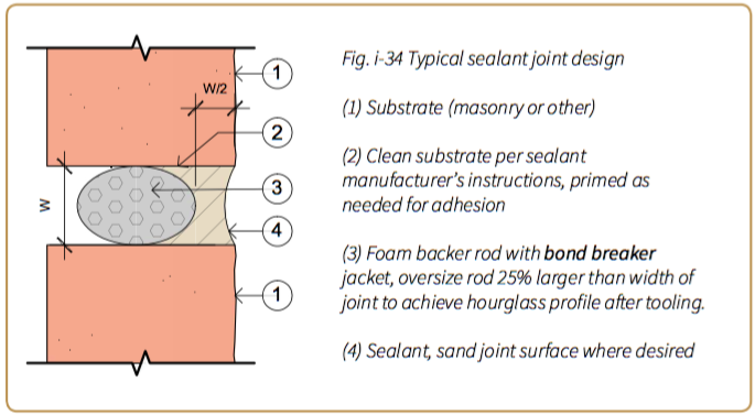

Fig. i-35 Typical sanded sealant joint below a window opening

Penetrations through masonry systems are common, including service penetrations, temporary scaffold tie-back supports, or structural penetrations such as knife plate connections as shown in Fig. i-38—which are a common method of supporting canopies, balcony structures, and building signs on new structures in the Northwest region. These penetrations are typically anchored to the building structure and penetrate the air and water control layers as shown in Fig. i-39; they may also penetrate the thermal control layer. In anchored masonry veneer applications, the veneer and wall structure move independent of one another. This movement must be accounted for in the design while maintaining continuity of the water-shedding surface and the air and water control layers.
Penetrations through the air and water control layers need to be detailed to prevent water intrusion and air leakage and to allow for an unobstructed drainage pathway around the penetration (behind the cladding). Two common practices for detailing around penetrations are shown in the flashing sequences in Fig. i-40 and Fig. i-41 on page i-57: a self-adhered flashing membrane and a fluid-applied flashing membrane, both applied around and onto the penetration. Pre-formed, gasketed boots may also be used and are typically detailed similarly to Fig. i-40.
Although Fig. i-40 and Fig. i-41 show a knife plate penetration, the flashing sequences may be used for most discreet penetrations through the masonry veneer. Large penetrations through the veneer (e.g., a continuous steel channel support, a unit exhaust vent, etc.) may require alterations to the sequence, such as a sheet-metal head flashing, to ensure adequate cladding support and unobstructed drainage at the face of the WRB system.
While detailing around penetrations is important, continuity of the air and water control layer at the penetration is equally important. This may require sealing holes and wire penetrations within electrical boxes or installing sealant between sleeves and pipes.
Penetrations that extend through thermal insulation layers should also be evaluated on a case-by-case basis for thermal bridging effects and condensation. These risks can be minimized by using lower-conductivity penetration materials (e.g., PVC in lieu of steel for sleeves or pipes).
Care must be taken when designing and detailing penetrations projecting through anchored masonry veneer. As discussed in “Locating Movement Joints” on page i-49, differential movement between the backup wall structure and veneer needs to be accommodated. Anticipate expansion of a clay masonry veneer and shrinkage of concrete and wood-framed structures. Additionally, weight applied to some connections (e.g., a balcony placed on a knife plate connection a er the masonry veneer is in place) can also introduce movement.
This guide recommends that penetrations through the water, air, and thermal control layers, or masonry veneer, are secured before the mason contractor begins work. Preplanning penetration locations and detailing can avoid schedule delays and cladding removals due to out-of-sequence installations.

Fig. i-38 Typical structural knife plate penetrations through an anchored masonry veneer prior to installation of exterior sealant joints or final cleaning
Fig. i-39 Typical structural knife plate penetrations flashed with a foil-faced self-adhered flashing membrane similar to the sequence in Fig. i-40 on page i-57. Also visible is a pre- formed penetration boot for a pipe penetration.
Sheet-Applied Air Barrier and WRB System – Flashing Sequence (Fig. i-40)
Fluid-Applied Air Barrier and WRB System – Flashing Sequence (Fig. i-41)
Further promote water diversion at the penetration by forming wire drip loops and sloping pipe penetrations away from the structure.

In the Northwest region, surface-applied clear water repellents are commonly applied to the surface of masonry veneer claddings and exposed CMU walls for the systems featured within this guide. Elastomeric coatings may also be used in targeted applications. The success of a clear water repellent or elastomeric coating is reliant on appropriate product selection, cleaning procedures, and application methods. Although these products have a number of uses, as described below, their use does not make up for poor masonry workmanship or detailing. This section covers cleaning and best practices for selection and application of clear water sealers and elastomeric coatings.
Cleaning of any mortar on grout smears, construction dirt, staining, contaminants, and possibly efflorescence from the construction phase is required prior to the application of clear water-repellent coatings. When masonry surfaces are to be opaque-coated, cleaning is only necessary to provide adequate adhesion between the coating and the masonry wall. A number of cleaning methods are available including hand, water, chemical, and abrasive.
Select cleaning procedures based on masonry unit and mortar colors, texture, and the type of existing debris or contaminants. In general, select the least-aggressive cleaning method necessary to remove debris and contaminates and to effectively clean the wall. Over-cleaning masonry products or using excessive abrasion can alter the appearance of the masonry veneer or CMU and can encourage premature weathering.
For all cleaning methods, test-clean an inconspicuous area of the wall to confirm the e effectiveness and acceptability of the cleaning method. Water-clean only when surface and ambient temperatures exceed 40 ̊F; even warmer temperatures may be required for applications of chemical cleaning products that rely on a chemical reaction to be effective.
ASTM D570332 and BIA Technical Note 2033 are helpful resources for determining appropriate cleaning procedures for clay masonry units, whereas NCMA TEK 8-4A34 provides helpful discussion on cleaning CMU block of various types and finishes. Also consult the masonry unit or CMU manufacturer and cleaning product manufacturer (where applicable) prior to cleaning.
A surface-applied clear water repellent is recommended for the systems in this guide that include adhered or anchored unglazed veneer or exterior-exposed CMU. Application of a clear water repellent can reduce water absorption of the veneer and CMU, as demonstrated in Fig. i-42, while preserving or enhancing natural appearance and minimizing the need for cleaning frequency. By reducing how much water the masonry cladding absorbs, less frequent wetting/drying and freezing/thawing cycles are expected to occur, reducing the likelihood of premature weathering and water-related damage and staining.
There are two primary types of repellents: penetrating or film-forming.
Of the two repellent types, penetrating repellents are recommended for use within the Northwest.
For unglazed clay masonry and CMU in the Northwest, a silane/siloxane blend clear water repellent is common. Silanes penetrate deep into the pores of clay masonry, while siloxanes are deposited closer to the masonry surface.
Both silanes and siloxanes chemically bond to clay masonry, CMU, and mortar in the presence of moisture and alkalinity. As a result, silane/siloxane- based repellents can provide 5 to 20 years of protection, making such blends a durable and relatively longer-lasting water repellent option.
Clear water repellent application to glazed masonry veneers is not recommended. Glazed surfaces reduce the penetrating ability of clear water repellent products, limiting the effectiveness of the application.
When selecting a clear water repellent, the following are characteristics and/or properties that are desirable for long-term performance:
Where anti-graffiti repellent properties are desired, consider using a vapor- permeable silicone-based or fluorosiloxane-based repellent with penetrating properties that is marked as an anti-graffiti repellent. The anti-graffiti repellent should provide similar vapor permeance and water penetration resistance to that listed above. The effectiveness of anti-graffiti properties is demonstrated through ASTM D708937 results, which may be used to compare the ease of graffiti removal.
Clear water repellents should not be used as a replacement for a water-resistive barrier or air barrier within a masonry system. Water repellents are also not effective at bridging cracks or filling voids that result from poor joint design/installation or from long-term building movement. Although clear water repellents will increase the masonry’s ability to shed water, a repellent will not prevent efflorescence as a result of water intrusion behind a masonry veneer and will require reapplication to be effective over the long-term service life of the building.
The following general procedures and considerations are the best practices for clear water repellent application:
☑Complete cladding sealant joints (e.g. around window and door perimeters and at expansion/control joints) prior to application. Sealant joints should be fully cured (typically 14 21 days) prior to cleaning and application.
☑Clean masonry substrates to remove debris and surface contaminates prior to water repellent application.
☑Protect areas that are not to receive water repellent. Prevent contact between clear water repellents and non-masonry products such as asphalt-based products, window glazing, and landscaping.
☑Avoid applying sealant when rain threatens, when windy, and when minimum water repellent application temperatures are not met.
☑Perform a mock-up to demonstrate protection, cleaning, and water repellent application procedures and for review of final masonry appearance.
☑Plan application extents to determine start and stop application locations; avoid overlap.
☑Apply water repellent in accordance with the repellent manufacturer’s installation instructions, including the application rate. General application requirements may include the following:
Elastomeric coatings reduce the amount of water absorbed by masonry substrates and also provide crack-bridging properties that help reduce water leaks. Elastomeric coatings are typically installed where additional water penetration resistance is desired and where a painted surface is visually acceptable. An example of an elastomeric-coated CMU wall is shown in Fig. i-44. Elastomeric coatings can serve as a water-shedding surface, water-resistive barrier, and air barrier on the exterior face of a masonry substrate when a UV-stable coating is used.
A vapor-permeable silicone or acrylic elastomeric coating with UV resistance and high elongation properties is recommended for a good coating. A vapor-permeable coating will allow the masonry substrate to dry and reduces the likelihood of salt buildup and bubbling or blistering of the coating.
When selecting an elastomeric coating, the following characteristics/properties are desirable for long-term performance:
Elastomeric coatings can exhibit staining and may be difficult to clean. Surface staining is largely attributed to surface wetting as a result of runoff below horizontal or sloped surfaces and penetrations including flashings, windows, and parapets. Therefore, staining can largely be reduced by minimizing water runoff onto coated wall areas. Sheet-metal drip edges (such as at window and door sills) are recommended to deflect water away from the surface of the masonry coating to help reduce staining.
The following general application procedures and considerations are the best practices for elastomeric coating application:
☑Include consideration for water-shedding and deflection in above-grade wall design. Use minimum 1/2-inch projected drip edges to minimize coating staining and runoff.
☑Provide a minimum 28-day cure for masonry grouts and adjacent concrete surfaces prior to application.
☑Seal all cracks and cladding joints as recommended by the coating manufacturer. Use appropriate joint design and backing at movement joints. Typically, cracks or holes 1/16-inch wide or larger require treatment.
☑Use block filler when required by the manufacturer. Some manufacturers may allow an additional application of coating in lieu of block filler.
☑Test the coating adhesion to confirm cleaning procedures and priming requirements to the masonry substrate and joint sealants. Use a mock-up for coating review prior to full-scale application.

Fig. i-42 Water droplets form on a brick veneer on which clear water repellent has been applied

Fig. i-43 Clear water repellent application at an anchored masonry veneer
A clear water repellent will not prevent efflorescence as a result of water intrusion behind a masonry veneer and will require reapplication to be effective over the long-term service life of the building.

Fig. i-44 Exposed CMU wall coated with elastomeric coating.
The long-term durability and performance (including aesthetic performance) of masonry cladding starts with good design, is implemented with sound construction practices, and is preserved with regular maintenance over the service life of the building. Because the focus of this guide is design and construction, this section addresses how good design can minimize the risk of two occurrences in masonry cladding: freeze-thaw cycles and efflorescence.
Freeze-thaw cycles can be described as repeated freezing and thawing of moisture within masonry pores as a result of temperature fluctuations. The occurrence of freeze-thaw cycles does not always result in damage but can if enough moisture exists within the masonry component to cause damage and the occurrence of these conditions are frequent. Eliminating either the moisture source or the occurrence of freezing temperatures can eliminate the risk of freeze-thaw damage.
The factors impacting both the occurrence of freeze-thaw cycles and the likelihood of resulting damage include climate, material properties, and building-specific design features and are described in the following sections.
Wet climates prone to rapid temperature swings and marine climates that experience freezing temperatures have a greater risk of freeze-thaw occurrence. Freeze-thaw occurrence is atypical in the Northwest region; however, it is more likely to occur in areas that experience freezing temperatures and experience high-to-extreme rainfall (see the Determining Building Enclosure Loads discussion on page i-16), particularly those areas of the Cascade Range and the Rocky Mountains.
Climate is a factor beyond the control of the designer and mason contractor; thus, material properties and building-specific design are of greater focus for minimizing freeze-thaw damage in higher-risk areas of the Northwest region.
Porosity, pore structure/size, material strength, and saturation coefficient of the masonry material may affect the occurrence of and subsequent damage due to freeze-thaw cycles.
While the direct relationships between these material properties and freeze-thaw occurrence is highly debated and not described here, the discussion within each system’s chapter provides recommendations for specifying masonry components that are appropriate for exterior applications and limit the risk of freeze-thaw damage.
Building-specific design concepts of masonry systems are within the control of the designer and can greatly reduce freeze-thaw occurrence and related damage. The following building-specific design concepts should be considered, especially within higher-risk areas of the Northwest region:
Note that many of the building-specific design concepts beneficial for ensuring the long-term durability of the masonry wall or veneer are also beneficial for the long-term performance of the system as a whole. The above-noted concepts also serve to reduce the likelihood of water leaks and heat loss/energy consumption and can improve the long-term durability of the structure and masonry cladding.
Efflorescence occurs when water-soluble alkali salts within the masonry unit, mortar, and/or grout are dissolved by water and migrate to the surface of the masonry wall or veneer. Water evaporates when it reaches the exposed surface of the masonry, leaving the salts behind—which typically appear as a white residue. Minimizing wetting of the cladding through good design, sound construction practices, and regular long-term maintenance can help prevent efflorescence. Refer to the Building-Specific Design discussion of this section and the recommended details at the end of each system chapter.
It is typical for some efflorescence to form on masonry veneer and walls systems immediately following installation due to moisture within the grout and mortar materials during placement. Should efflorescence be observed following the final cleaning of the masonry veneer a er installation, a source of moisture may be present and should be investigated and repaired as needed.
Historically, freeze-thaw occurrence, has not been a problem with well- designed and properly constructed masonry structures in the Northwest region.
In-depth discussion of sound construction practices in the field and long-term maintenance of masonry cladding is beyond the focus on this guide; however, we remind the reader to seek qualified mason contractors to perform work within the Northwest region to ensure quality installation of masonry materials. Additional numerous resources addressing the long-term care and maintenance of masonry veneer and wall systems are available through the organizations listed in the References section at the end of this guide.

Fig. i-45 Example of efflorescence on anchored masonry veneer